This website uses cookies to ensure you get the best experience on our website. To read our full cookie policy please click here.
Model 1150 On-line Conductivity Monitoring and Control System
In-Line Monitoring And Controlling Of Electrical Conductivity Of Fuels In a Variable Stream as specified in ASTM D2624.
To reduce the hazards of electrical charge build up that can occur especially during high pumping rates of low conductivity materials through filters, additives are added to the product. Emcee Electronics, Inc. offers the Model 1150 Staticon® System (listed in ASTM D 2624) that has the capability to monitor and control conductivity of such products in a variable moving stream.
The system can control the additive injection rate to maintain a preset level and has the ability to turn off the main pumps when either a high or low preset limit has been exceeded. The basic System consists of a Control, a Barrier, a Fuel Cell Module, a desktop PC and an optional injector pump is offered. Intrinsically safe approvals have been received from the applicable domestic and foreign agencies, such as Underwriters Laboratories (UL) U.S. (UL) Canada and LCIE (Registered Quality) Europe.
Model 1150 Staticon Monitoring & Control System
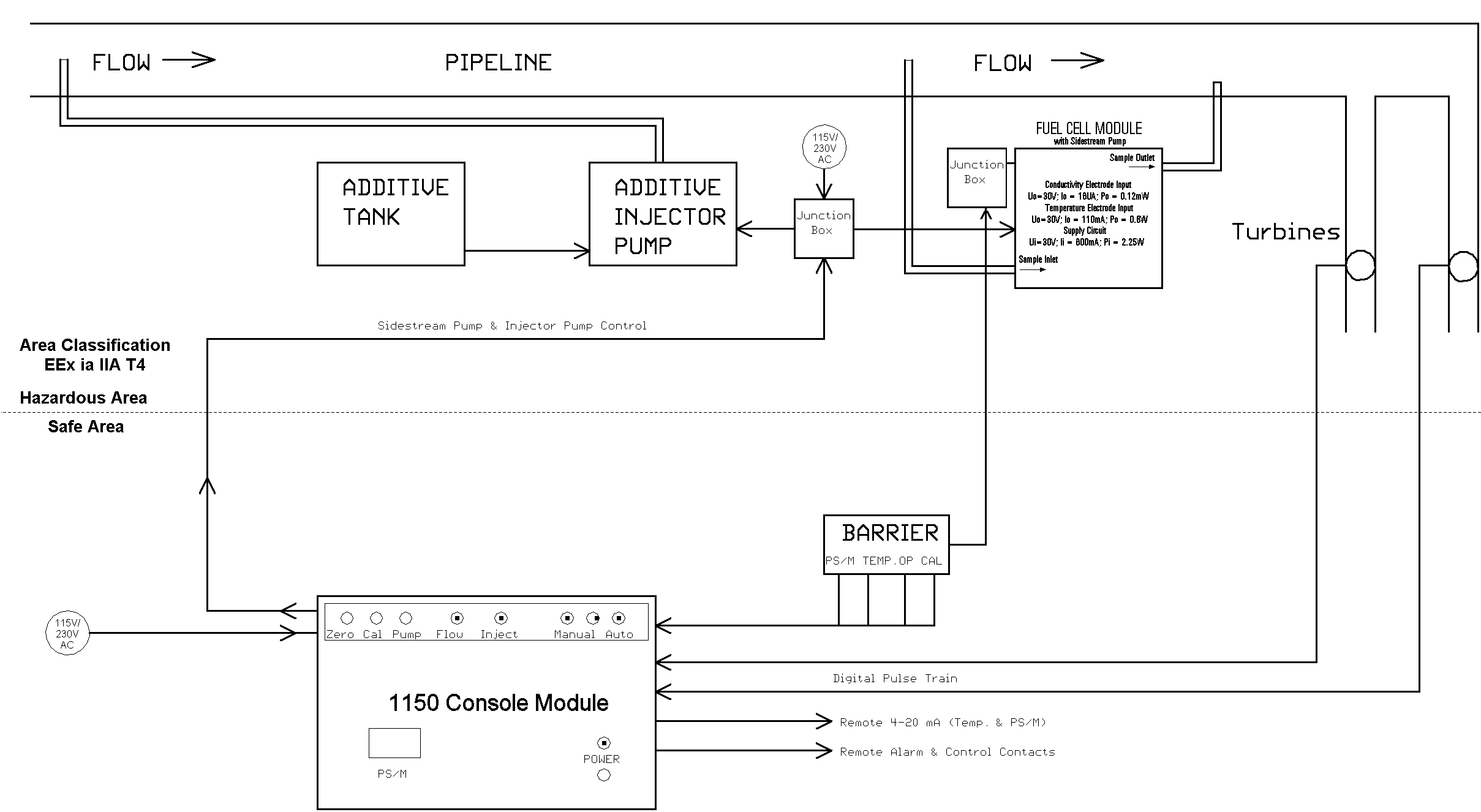
The requested conductivity level and limits are set in the Control Module (Fig. 1). The test cell in the Fuel Cell Module generates conductivity and temperature data that is passed through the Barrier Module to the Console Module where it is processed utilising a microprocessor, stored, and displayed. The data is also used to control the additive injection rate to maintain the requested conductivity level. The injection rate varies to compensate for variations in additive strength and temperature. The Console Module, as shown, can handle 2 streams by adding an additional Fuel Cell Module and barriers to the existing Barrier Module. Various other conductivity ranges are available.
 The Fuel Cell Module houses the test cell and an explosion proof pump. The product is extracted from the pipeline, passes through the test cell at a constant flow rate that is maintained by the pump, and is reintroduced downstream into the pipeline.
The Barrier Module provides the intrinsic safety provisions to prevent high voltages from reaching the test cell in the Fuel Module.
 An optional Additive Injector Assembly and the Fuel Cell Module with cover removed is also shown.
 1150 Intrinsic Safety Diagram and operation
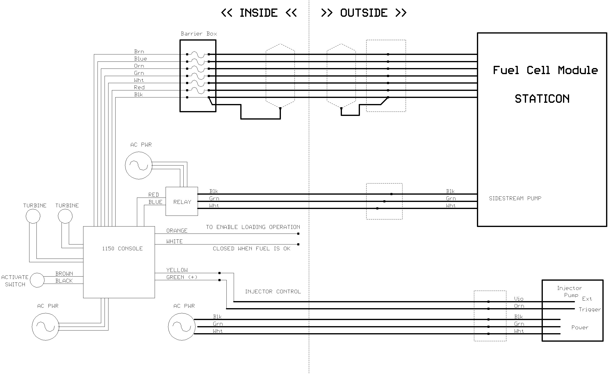
 1150 System Connections
Dimensions:
Console Module
270x508x406mm - 23 Kg
Fuel Cell
610x450x200mm - 32 Kg

